

DUAL PATH VORTEX TUBE TECHNOLOGY
UVI's Dual Path Vortex Tube provides for intensive energy division and effective spot heating.
How the Dual Path Vortex Tube Works
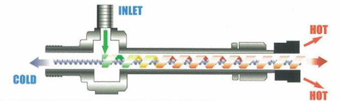
The Dual Path Vortex Tube (VT) is a specially designed cylindrical device with no moving parts. In the Vortex Tube a high pressure gas expands in the unit’s tangential inlet nozzles down to the delivery pressure. While in the VT’s cylindrical part, the rotating low-pressure gas undergoes energy division (vortex phenomenon), forming two currents: the cold that is located in the VT’s center and the hot at the unit’s periphery, moving along the VT’s internal walls. The cold and the hot currents exit the VT separately as the cold and the hot outlets.
In the proprietary UVI Self-Heating Vortex Tube, the generated hot gas, prior to exiting the VT, is used to warm the unit inlet nozzles (spot heating) thus eliminating the likelihood of depressurizing gas freezing (self-heating provision).
Intensity of the vortex energy division depends on ratio of the VT inlet and outlet pressures and is not affected by the gas flow rate through the unit. The actual temperatures of the VT cold and hot outlet are expressed as follows:
T cold = T inlet - ∆T Joule-Thomson - ∆ T (vortex, cold);
T hot = T inlet - ∆T Joule-Thomson + ∆ T (vortex, hot).
A valve at the VT hot outlet is used to set a desirable ratio between the VT cold and hot outputs.
In operations with a Dual and a Single Path vortex tube an increase in Cp/Cv value of the working medium results in a greater vortex energy division in the feeding gas.
Applications
- Pipeline Pressure Regulation Stations
- Pressure To Power Technologies
- Fuel gas conditioning at Power Plants
- LNG Feed Precool
- Well Head Gas Conditioning
Generally, in the course of Dual Stream Vortex Tube industrial applications with natural gas, there is the possibility to negate a Joule-Thomson temperature drop in an inlet high pressure flow.
Examples (click to enlarge)


