VACUUM VORTEX TUBE (VVT)
The proprietary Vacuum Vortex Tube (VVT) can generate energy division of atmospheric air or any other gaseous medium in order to generate heating and/or cooling duty.
System Overview

Configuration
The VVT is available in two configurations
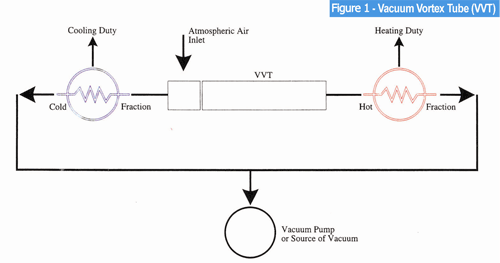
- Two Flows VVT design: A conventional design that produces the vacuumed cold and vacuumed hot flows (see diagram).
- One Flow VVT design: This design converts the whole inlet flow into a vacuumed cold air. Accordingly, the cooling duty generated can be utilized directly or through a heat exchanger.
Example Effectiveness
The VVT thermal efficiency e.g. ‘cold’ and ‘hot’ flows net temperature increment ΔT is roughly proportional to rarefaction in the cold and the hot flows; i.e. to the differential between the actual absolute pressure in the vacuumed vortex discharge flow and the atmospheric absolute pressure (30Hg).
Some magnitudes of ΔT at different rarefactions and at the cold and hot flows split of 50%:50% are shown below.
| Cold/hot flow absolute pressure, Hg |
Temperature increment, ΔT°F |
| 20 | 31 |
| 15 | 50 |
| 10 | 70 |
Since air feeds the VVT without first being pressurized, the VVT when used as a cold generator is highly efficient, as it does not have any latent heat, which is often typical for schemes utilizing compressed gases.
The cooling and heating or cooling duty created in the VVT can be utilized directly or through a heat exchanger as shown in the diagram here.

